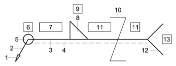
Levey jennings chart template free giordano polo shirt size chart orb chart go grow glow foods chart for kids android pie chart example code sally beauty ion color. A drawing of the location of elements of a welding symbol and how to put it all together.

ISO 25531992 2 Welded brazed and soldered joints Symbolic representation on drawings 3 ISO 5817 Welding Fusion-welded joints in steel nickel titanium and their alloys beam welding excluded Quality levels for imperfections 4 ISO 6947 Welding and allied processes Welding positions 5.
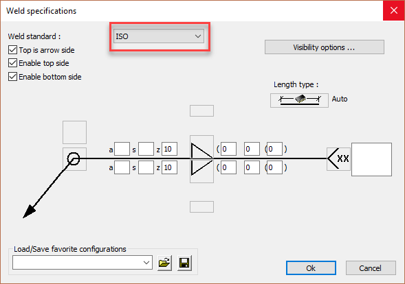
Iso weld symbol chart. If the dashed line is above the full line then the symbol for the nearside weld is drawn below the reference line and the symbol for the far side weld is above the dashed line Fillet Weld Sizing With the ISO system the weld size is placed to the left of the weld symbol and is preceded by the letters. Z a or s depending on whether the leg length or throat thickness is to be specified. ISO 25532013E 31 welding symbol symbol consisting of an arrow line and a reference line and which may also include elementary and supplementary symbols dimensions andor tail used on technical drawings to indicate welded joint type location and joint preparation Note 1 to entry.
32 basic welding symbol. The drawing will show two points like an X and a Y for example between sections needing welding. The arrows of the symbol between the two letters indicate that a weld needs to run the full length between the two marks.
This symbol has a flag showing the weld needs to be done on site not in the workshop. Just as a flag is positioned to mark a countrys site so this flag indicates. Weld With Flat Face.
The dotted line indicates the weld side. The symbol on the near and far side represent the type of weld surface. Weld With Convex Face.
The near side or far side of the weld is a convex surface. Weld With Concave Face. The weld or the opposite surface is concave in nature.
Iso 2553 Weld Symbols Chart Source. The chart below isnt really being dishonest worrying the data but its misleading. Bar charts are also very handy if you would like to discover more about the frequency of particular events eg.
The frequency of e-mails you receive over the day. Line chartLine charts are rather better than column charts or bar charts for revealing. An Explanation of the Basic Welding Symbols With Charts - Google Docs Author.
ˇˆˇ ˇ ˆ ˇˇˆ. ISO Welding Symbol Chart 03172010 1034 PM Blodgetts Design of Weldments or Design of Welded Structures available from the Lincoln Arc Welding Institute at a very reasonable price have this and other valuable information. The weld symbol gives you information of the type of weld and is usually a part of the welding symbol.
The weld symbol is placed above the reference line of the welding symbol. Back to menu Basic weld symbols. In the following chart you can see the basic AWS weld symbols groove symbols and also supplementary weld symbols.
Backing bar Designates the backing bar to be used on the back of the weld. If it has R in it it should be removed after welding. Spacer This symbol indicates the type and the dimension of the spacer that is inserted between the welded pieces.
Weld all around It signals that the weld is to be made over the entire circumference. Iso 2553 Weld Symbol Chart This engineering drawing present weld type symbols and fillet weld symbols. The weld type symbol is typically placed above or below the center of the reference line depending on which side of the joint its on.
The symbol is interpreted as a simplified cross-section of the weld. Range of approval restricted to the EN439 gas symbol Or Restricted to Nominal composition Used in test if no EN439 code exists. A weld made without a backing gas also approves welding with a backing gas.
The symbols and conventions used in welding documentation are specified in national and international standards such as ISO 2553 Welded brazed and soldered joints – Symbolic representation on drawings and ISO 4063 Welding and allied processes – Nomenclature of processes and reference numbers. The US standard symbols are outlined by the American National Standards Institute and the American Welding. A chart of the supplementary symbols.
A drawing of the location of elements of a welding symbol and how to put it all together. Isometric views of basic joints identification of arrow side and other side joint examples. Typical welding symbols examples.
Download an AutoCAD DWG version of the Weld Symbols Chart. The symbols and conventions used in welding documentation are specified in national and international standards such as ISO 2553 Welded brazed and soldered joints – Symbolic representation on drawings and ISO 4063 Welding and allied processes – Nomenclature of processes and reference numbers. The US standard symbols are outlined by the American National Standards Institute and the American.
Addition of a note in the tail of the welding symbol Other symbols in accordance with ISO 1302 may be used to specify surface finish. C The toes shall be blended smoothly by welding or finishing. Processing details may be specified in the work instructions or WPS.
D The weld run sequence may be indicated on the drawing eg. By use of multiple reference lines a note in the. Iso weld symbol chart - elements location of a welding symbol also welding symbol standard location of elements are given below and welding symbol standard location of elements are given below.
Levey jennings chart template free giordano polo shirt size chart orb chart go grow glow foods chart for kids android pie chart example code sally beauty ion color. ISO 25531992 2 Welded brazed and soldered joints Symbolic representation on drawings 3 ISO 5817 Welding Fusion-welded joints in steel nickel titanium and their alloys beam welding excluded Quality levels for imperfections 4 ISO 6947 Welding and allied processes Welding positions 5. When you will watch this complete lecture you will have great understanding of1 ISO 2553 Welding Symbols BS EN 22553 Welding Symbols2 Fillet weld dimen.
Symbol consisting of an arrow line and a reference line and which may also include elementary and supplementary symbols dimensions andor tail used on technical drawings to indicate welded joint type location and joint preparation. Note 1 to entry.